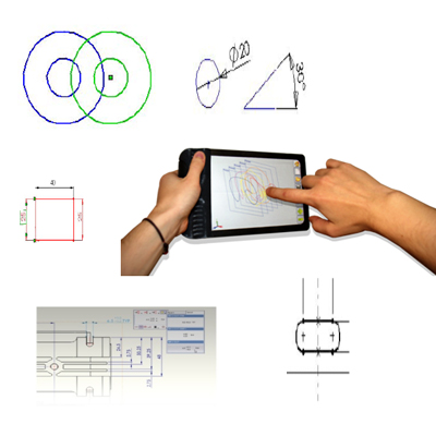
- Easy 2D Sketch creation & modification according to Design Intent
Smart Dimensions to create Linier, Angular, Aligned, Circular etc
- Creates Automatic Sketch Relations
Automatic Notification of Sketch States (Under Defined, Fully Defined & Over Defined)
- Automatic Sketch Operations to Repair Sketches
Creates Automatic Construction Entities like Center line, Center Marks, Points, Axis etc
- Automatic Highlights open Counters & Overlap Counters
Ready options to create Parabola, Hyperbola & Conics
- Improves visualization and communication
Data Migration tools to Import or Export
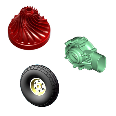
- Extrude, Loft, Standard hole wizard to generate most of the Mechanical Parts
All 3D models & 2D drawings are synchronized
- Different types of Geometry Patterns
Design Tables & Configuration to automate design
- Directly Modeling & Editing (Instant 3D)
Inbuilt Large Material Library
- Instantly Analyze Mass properties and Volume, Moments of Inertia, CG, etc
- Drag & Drop components to Assembly creates Automatic Relations
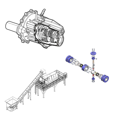
- Exploded views to Simplify Assembly Sequence
- Creates and Updates Automatic bill of Materials (BOM)
- Check Collision & Interference between Components
- Compare Alignment of Holes created using SolidWorks Hole Wizard
- Top down Approach helps to handle large Assemblies
- Skeleton Model Increases Flexibilities in Assembling the Parts
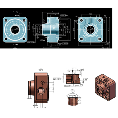
- Creates 2D views as per International Standards like DIN, ASME, ANSI, ISO, GB etc
- Automatic Projected, Section, Detailed, Alternate Position Views, etc
- Drag and Drop Predefined Drawing views
- Creates Automatic & Associated BOM
- Optional First or Third Angle Projection view Orientation
- Automatic Scaling
- Verify Designs Against Company Standards
- Build Checks— Set up and save specific Design and Drafting Checks
- Check Specifically for fonts, dimension Arrows, Units, and other Documentation details
- Compare your Drawing to Past Results from Reviews of other Drawings
- Automated Revision Control
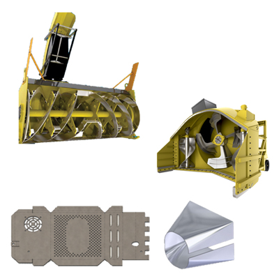
- Convert Imported CAD models to SolidWorks Sheet Metal Model
- Automatically Input your own bend radius, thickness, and K- Factor
- Generate Base, Edge, Miter, and Swept Flanges
- Generate bends, including Lofted Bends, Sketched Bends, and more
- Use Bend Tables for bend allowance/bend deduction
- Use Forming Tools to create features like ribs, louvers, lances, embosses
- Add weld details to sheet metal parts on models or drawings
- Automatically flatten parts to generate flat patterns (Development drawing)
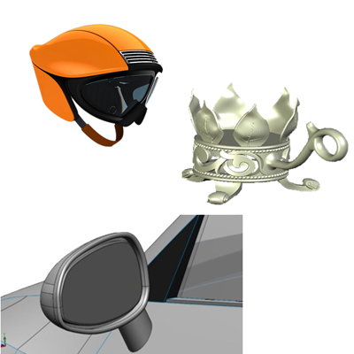
- Create Complex & Esthetic Geometry using Swept, Planar & Ruled Surfaces
- Create Organic and Stylized Shapes using Boundary Surface, Surface Fill, Freeform Radiated Surface, M Surface
- Edit model using Move/Copy Face, Instant3D, Copy Surface, Replace Face, Healing, Knit, Trim, and Extend
- Surface analysis tools: Gaussian, Draft, Undercut, Thickness, Curvature, Min radius, Zebra Stripes, Deviation\ analysis, and Symmetry Check
- Geometry Import and Repair and Healing tools
- Import options as a SolidWorks Drawing or SolidWorks Part
To read any modify 2D Data, Powerful tool Draft Sight
- Orienting and aligning 2D Sketches
Blocks and Mechanism for Sketches
- Convert all entity fully defined automatically
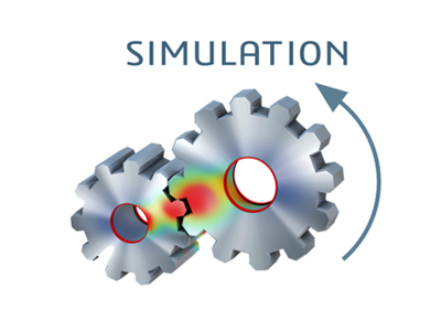
- SolidWorks SimulationXpress is a first- Pass analysis tool
- Giving you the ability to do basic stress analysis on individual parts
- Quickly determine effects of force and pressure, and generate reports to document results
- Guided set up for Inexperienced Design Engineers
- Easy to Learn & Validate your part design
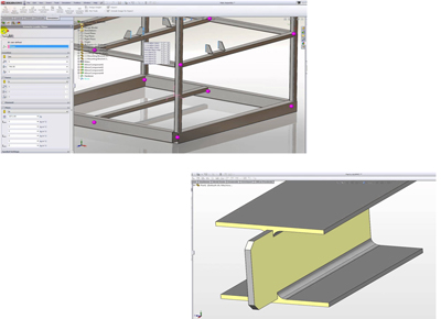
- Work from a library of pre-defined structural shapes
Generate 3D sketch lines for structural profiles to follow
- Automatically trim structural members at intersections
Add stiffening plates, gussets, and end caps
- Add optional weld beads to the design
Generate drawings, BOMs, cut lists, and other manufacturing documentation
- Geometry Import, Repair, and Healing tools
Draft Analysis, Undercut Analysis, and Thickness Analysis tools
- Parting line tools
Parting surface tools
- Automated “fill surface” capability for easy shutoff surface creation
Core and Cavity splitting tools
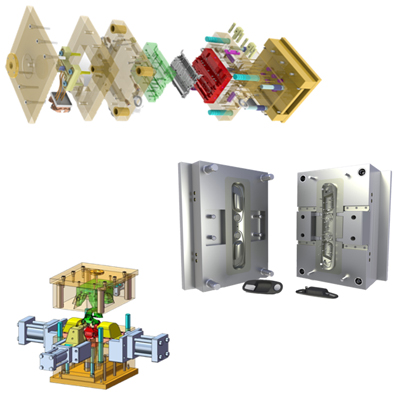
- 3D mold bases available on-line and directly from major mold suppliers
SolidWorks configurations to create customizable configurations of molds and mold components
- Compare Part tools to visually see in 3D what geometry was added or removed when design changes occur
Mold filling simulation with SW Plastics
- Production quality mold drawing creation tools
- Apply Appearances – Adjust elements of your model including color, texture, and illumination
Apply Scenes- Set and control the Background and surroundings
- Decals – for labeling, branding, stickers, instrument faces, etc
Integrated Preview – View your output in a preview window before fully rendering
- Rendering Options – Control output image resolution, animation frame rates, etc
Final Renderer – Generate detailed output after your preview
- Rendering Scheduler – Set up your rendering to run during off-hours
Rendering templates – Save rendering setting for later use to ensure consistent output
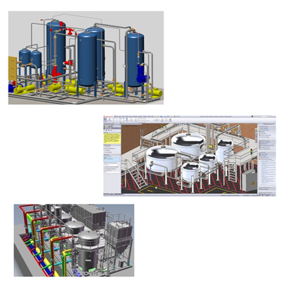
- Create piping system designs with butt welded, socket welded, threaded and other connections
Create flexible or rigid tubing lines
- Automate placement of supports and hangers for all lines
Generate bend tables for tube routes to support manufacturing
- Calculate cut lengths for all pipe and tube runs
Auto- route pipe/tube paths through the design
- Ensure minimum bend radii in flexible tube systems
Export tubing/piping bend tables to CNC benders
- Automatically create bill of material (BOM), cut lists, bend tables and other mfg documentation
Access a CAD library of piping and tubing components
- Component material , connections, and relationships defined
Products can be tested for strength and safety, and the kinematics fully analyzed
- A wide variety of geometry types are supported so you can simulate the real world performance
Solid, thin-walled, and structural features for Complex geometry
- Beam element can be applied for structural analysis
Shell elements can be applied for very thin parts like Sheet Metal
- Can create study for Part & Assemblies
